Adding a Drain for Heating/Cooling Equipment
About the Project
I would call this a project of opportunity. It was possible because i was installing a new insulated wall to cover the uninsulated concrete wall along the end of the basement.
This house had a heat recovery air exchanger when we bought it. We upgraded that one to a HEPA unit 2 years ago. The original unit had a water drain tube that ran to the perimeter trough around the concrete floor. The trough runs to a floor drain in the basement corner. I kept the new air exchanger drain tube in the same place. Its about 25 feet from the corner floor drain.

There were two furnaces in the house, one wood and one oil fired. The latter also supplied domestic hot water. We removed the furnaces and install baseboard electric heat as the secondary heat and a 48000 BTU LG Mini-Split with 4 inside air handling units as the primary heating/cooling system. Each air handler unit has a water drain tube to take away any condensation. The living room and one basement unit drain tubes exit out the wall and onto the asphalt outside. That, of course, creates ice outside in winter. These drain tubes are about 5 feet from the outside compressor unit.


Here is a not-to-scale sketch of the existing drains for the air handlers and the air exchanger. This is mainly to show location of the items shown above.

Here is the design for the new drain pipe going to the floor drain.

Tools and Materials
This was a relatively simple install.
I used a pull-cut Japanese saw to cut the pipe, a file to remove burrs, and PVC adhesive to make the joins,
The main pipe run was 3/4 white PVC pipe and fittings (90s, 45s, couplings and a Tee. Two 3/4 by 1 adapters were used along with a short length of 1 inch pipe for the air handler drains to fit into.
The pipe was suspended on carriers made from pieces of steel stud and screwed to the steel studs at the appropriate height to give a slope of 1″ in 48″.
Installing the Drain Pipe
These images show some of the installation sequence.
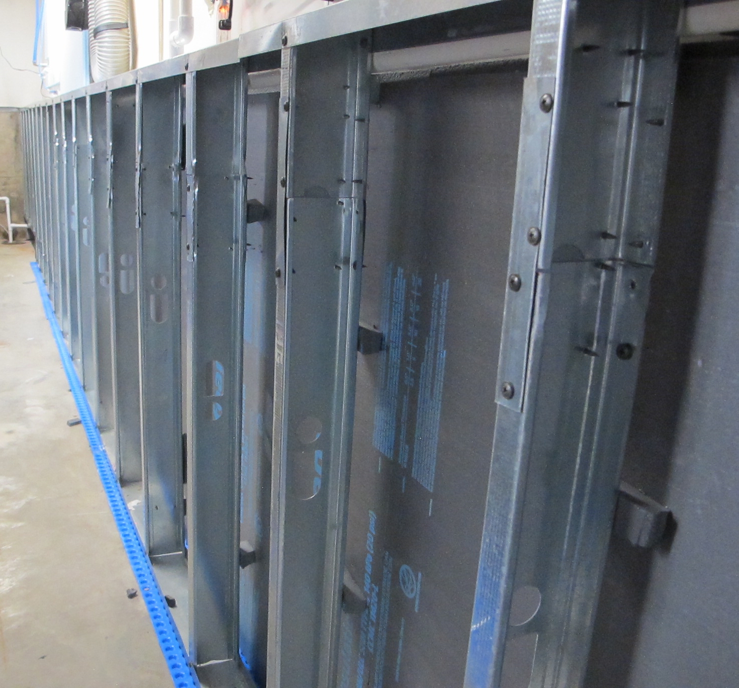
Steel-Stud-Wall-Looking-towards-the-Floor-Drain
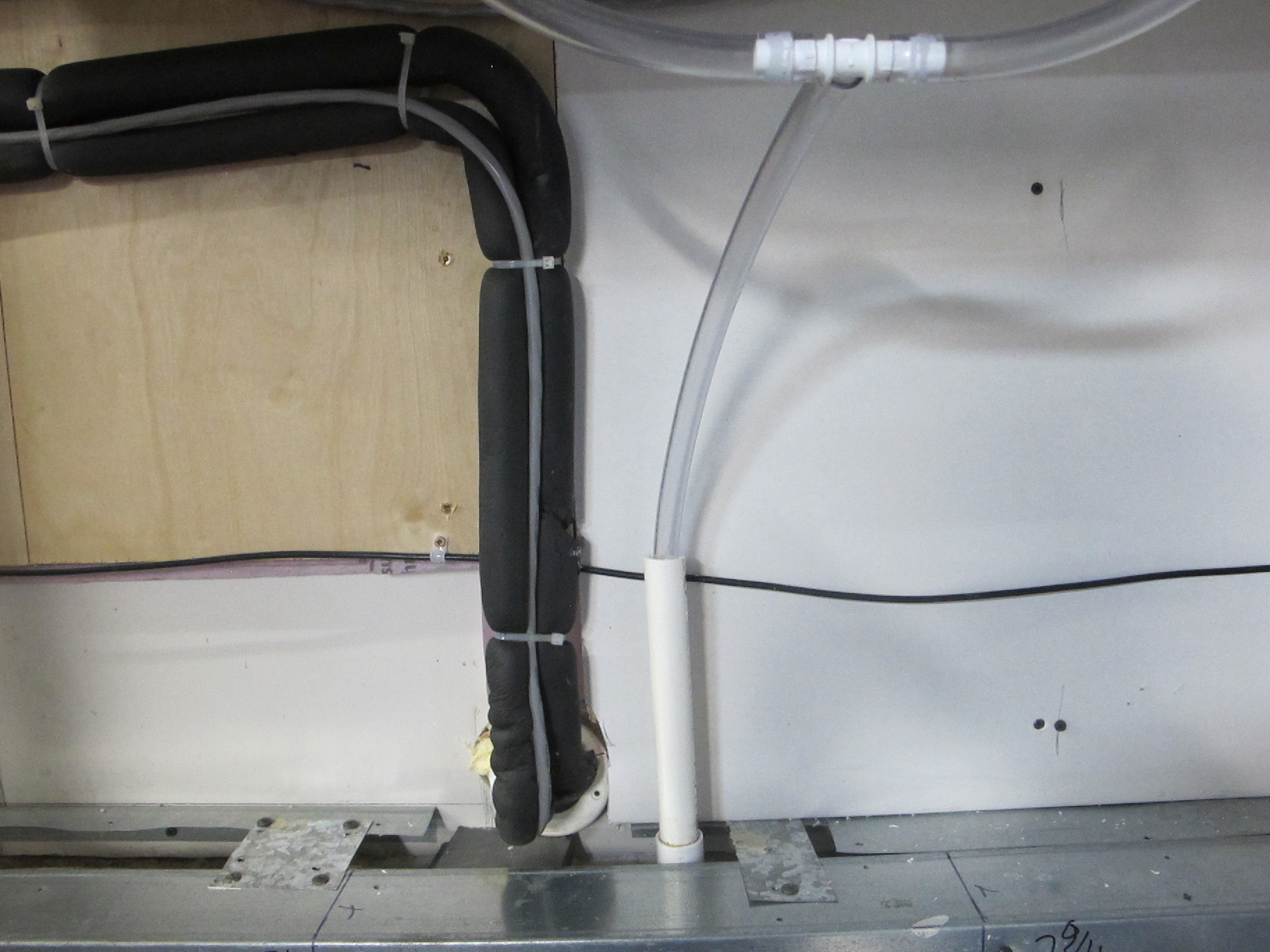
Pipe-Along-Top-of-Wall
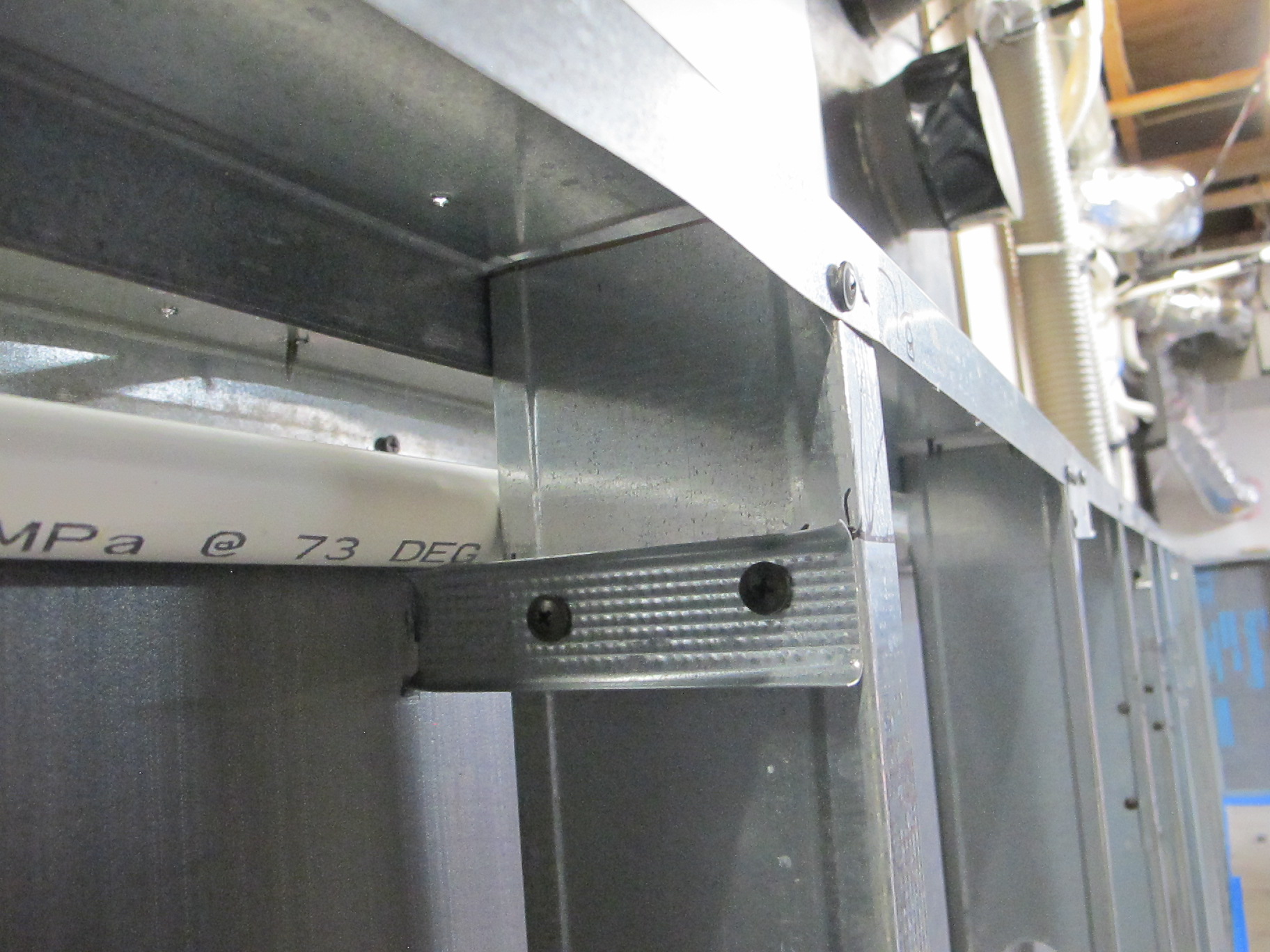
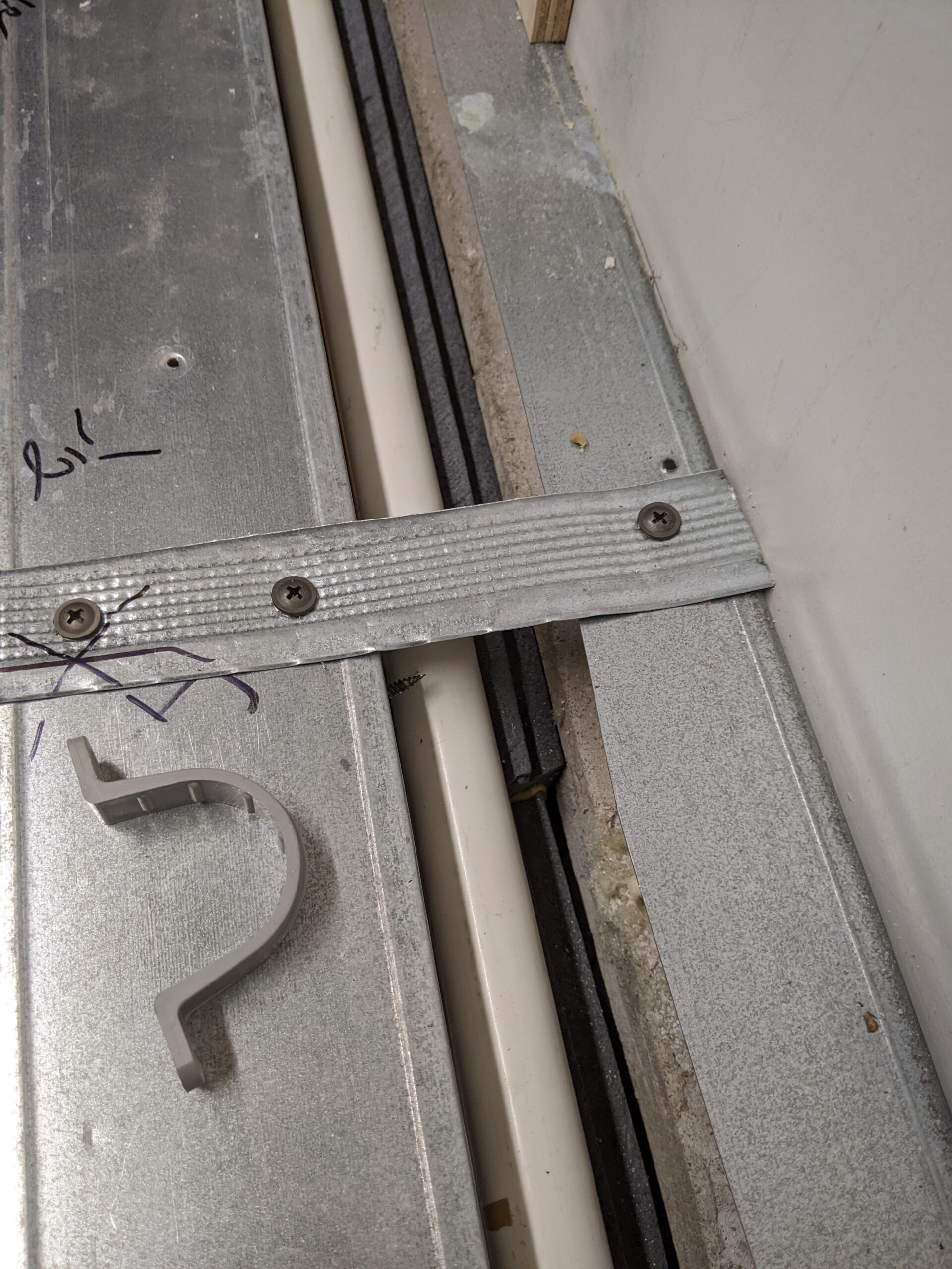
Pipe-Bracket-from-Steel-Stud-Offcut.
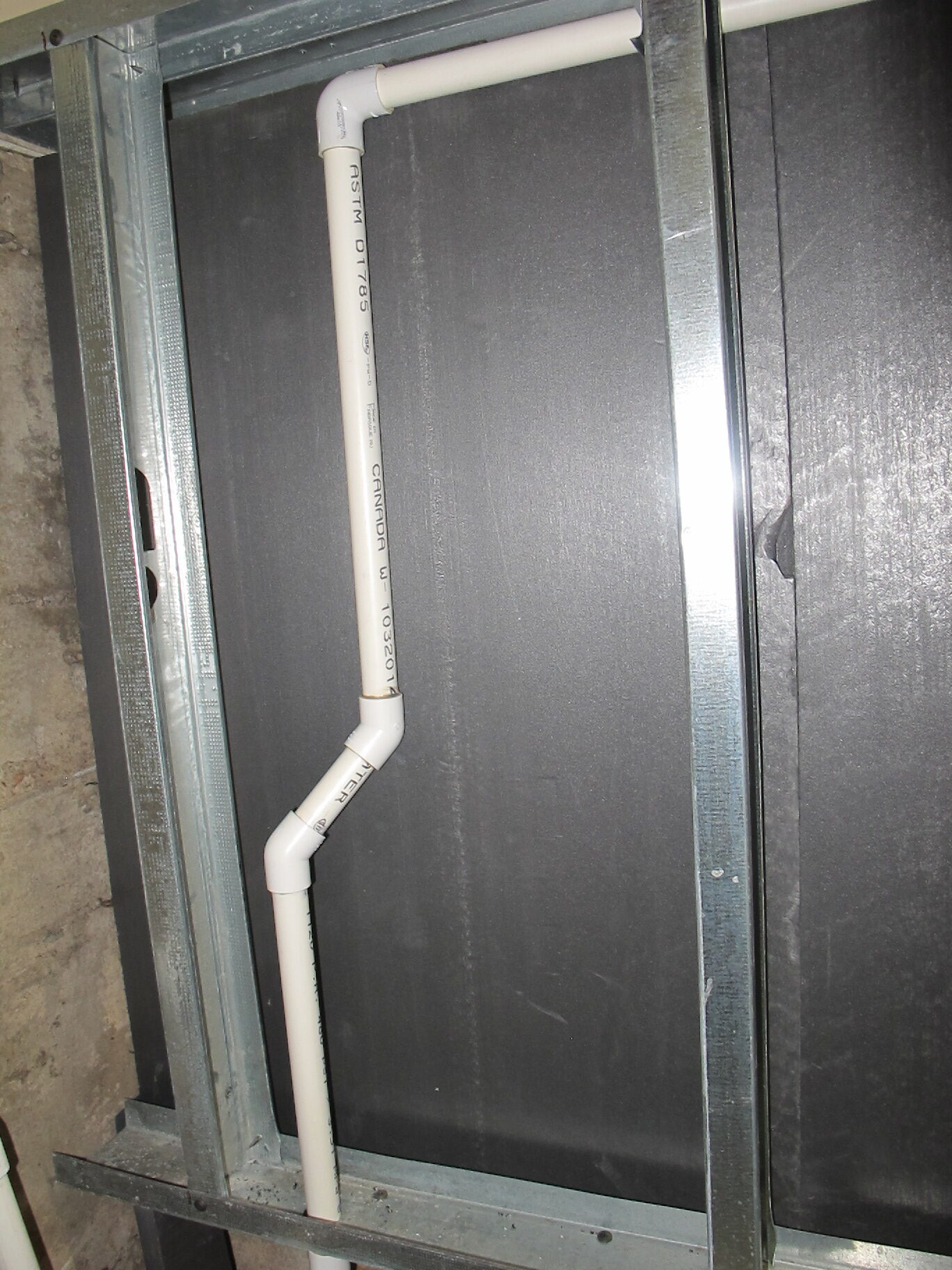
Pipe-Down-to-Drain
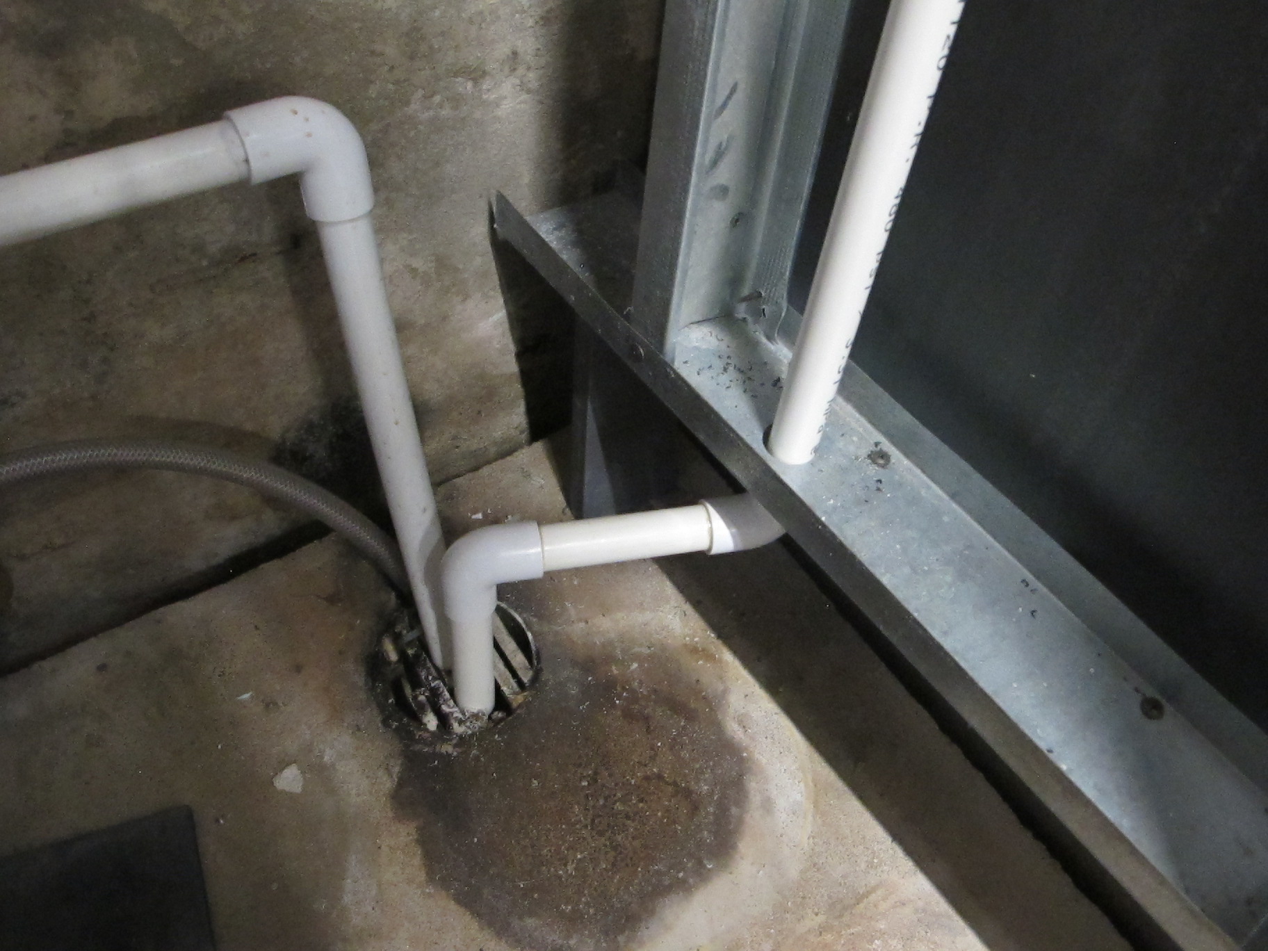
Pipe-Into_Drain
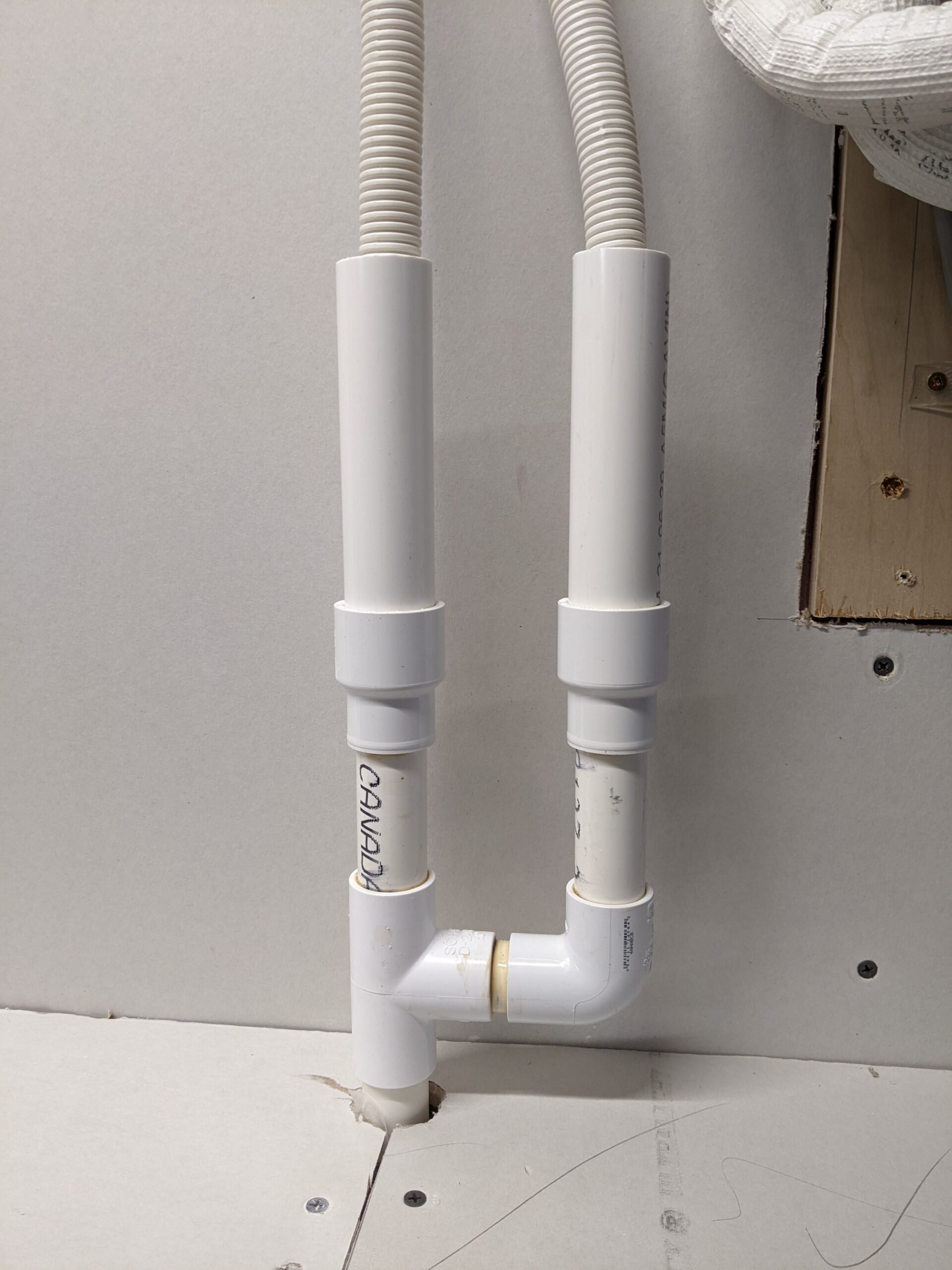
Air-Handler-Drains-into-Pipe
0 Comments